The ugly face of circuit tracking, Part 2
I posted before the first install about some of the challenges in nomenclature, metadata storage, and mapping abilities of having so many fiber patches and logical portions to keep track of in an optical network. I also talked about the impending system to keep track of it all. I'm happy to say that the system appears to be very well fleshed out. I saw an optical path illustrated on one of our other optical networks we manage, ILight. It's just simply stunning.
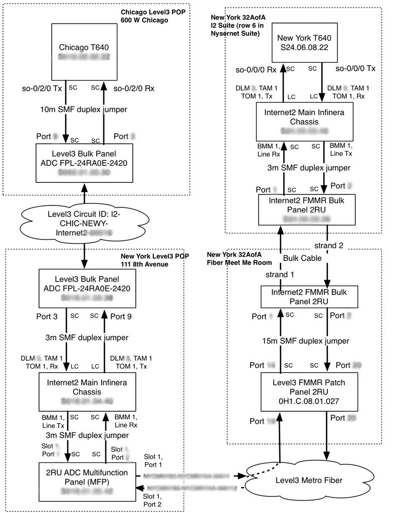
So I sat down tonight and spent an hour diagraming up the path of the first backbone circuit between Chicago and New York for the database guys to work on getting into the database. I suspect the different numbering schemes of the various fiber distribution panels (FDPs) is going to trip them up, but this is a good dry run.
So, what's good enough for our database programmers is good enough for you. Here's the diagram I sent him (with some key bits of information blurred out to protect both their nakedness and true values) along with the explanation I sent that described the data path. It's a bit more detail on just how challenging this sort of thing is to track on a large scale. Everyone I've talked with, aside from major carriers, does this sort of thing on spreadsheets spread across several engineers laptops. Getting this information into a database represents a quantum leap in the way we handle our POP metadata. I'm quite proud to work with colleagues that can think this hard about a problem and come up with such an elegant solution. I would suggest that you click on the diagram and open it in another window while reading along:
See you all in Chicago.
So I sat down tonight and spent an hour diagraming up the path of the first backbone circuit between Chicago and New York for the database guys to work on getting into the database. I suspect the different numbering schemes of the various fiber distribution panels (FDPs) is going to trip them up, but this is a good dry run.
So, what's good enough for our database programmers is good enough for you. Here's the diagram I sent him (with some key bits of information blurred out to protect both their nakedness and true values) along with the explanation I sent that described the data path. It's a bit more detail on just how challenging this sort of thing is to track on a large scale. Everyone I've talked with, aside from major carriers, does this sort of thing on spreadsheets spread across several engineers laptops. Getting this information into a database represents a quantum leap in the way we handle our POP metadata. I'm quite proud to work with colleagues that can think this hard about a problem and come up with such an elegant solution. I would suggest that you click on the diagram and open it in another window while reading along:
I know the GLIF has been doing some work on this sort of thing and have heard a few folks talk about going through the motion of modeling portions of their network in Network Description Language. I honestly don't know what the underlying mechanism here is, but perhaps that's a good topic for another post from someone who can speak more definitively...Starting in Chicago....
The T640 connects to a Level3 single RU panel in the position indicated. I've indicated the connector types on each end throughout. It terminates 24 simplex SMF fibers. They come prelabled from the manufacturer in the following manner: the chassis is split in half with 12 strands on the left and the next 12 on the right. The top row on the left starts with port 1 and increases to the right until it gets to the middle (so, 1-6). Then the numbers pick up under that (7-12). The right side is similar with number 13 starting on the top left port of the right side and increasing to 18. Under that is 19 through 24. Level3's standard is to use ports on top of each other rather than the ports next to each other. That means, instead of seeing port assignments 1 &2, you'll see 1 and 7.
That bulk panel runs to some Level3 panel somewhere and into their transport cloud. Eventually it ends up on another bulk panel in New York at the ports indicated.
That New York bulk panel is at 111 8th Avenue, but we have our router at 32 Avenue of the Americas (32AoA). To get this signal between buildings Internet2 purchased Infinera metro DWDM boxes that we manage and Level3 metro fiber between buildings. The client signal from Level3's bulk panel (framed at OC-192) drops out of the bulk panel into a client port on the Infinera (the DLM in slot X of the chassis, the TAM card in slot X of the DLM, and the TOM in port X of the TAM) From there, it is muxed onto a DWDM network between 111 8th Avenue and 32AoA. So, on the diagram from BMM to BMM on the two New York Infineras is a DWDM-capable path that can carry up to 40 circuits.
We don't really have a separate naming convention for those circuits and I went with the same name as the Level3 circuit ID. It occurs to me that we could probably make up a better circuit ID for that portion of the circuit. Perhaps something like NEWY1118TH-NEWY32AOA-0001.
The Level3 metro fiber lands in the 111 8th Avenue suite on a Level3-provided multifunction panel. It has 4 "slots", each accepting a different type of fiber, copper, or coaxial termination model. It's essentially just a piece of sheet metal holding a bunch of couplers together. Our BMM connects to ports 1 and 2 on the first slot. The particular module in that slot has 6 SC fiber couplers in two rows, numbered from left to right (so, 1-3 on the first row and 4-6 on the second row)
From that MFP, Level3 has two dark fiber strands between 111 8th Ave and 32AofA. I didn't indicate in the diagram, but the fiber in port 1 of the 111 8th Ave MFP is connected to strand 11 (the top strand) on the run betwen buildings. The circuit ID listed for the dark fiber is Level3's.
The Level3 dark fiber terminates onto a patch panel in the fiber meet me room (FMMR) in 32AofA. From there, Internet2 is responsible for a 15m jumper over to Internet2's panel in the FMMR. I don't have the rack assignment for that in my notes, but I'll try and get it from Nysernet. The I2 panel in the FMMR terminates a 48-strand bulk cable that runs over to a Leviton FDP in our suite. The Leviton FDP spec sheet is attached. It's a 2RU box populated with four 12-strand modules. Best to just look at the photos here to get the numbering scheme:
http://www.pbase.com/i2net/image/70365530/original
The upper left is port 1, numbers increase to the right. 1-6 on the top row, 7-12 on the second row, 13-18 on the third row and 19-24 on the fourth row.
From the front of that panel, the composite metro DWDM signal goes into the Infinera BMM. From there, the Infinera client optics drop it to the T640 as a framed OC-192.
As you can tell, there's quite a bit of variation in the patch panels in the path and their numbering schemes. The database will need to accomodate that.
Here's the photo of our original whiteboard discussion of how these circuits are tracked:
http://photos1.blogger.com/blogger/4378/146/1600/IMG_0024.jpg
Recall that we were going to have one overall circuit ID for this entire end to end path. That hasn't really been specified yet in this discussion. I've been calling the circuit by the Level3 circuit ID name in all labels because we don't yet have the database ready to link disparate circuit IDs together into something someone would be able to figure out without the diagram I've drawn up.
See you all in Chicago.
posted by Chris Robb at 12/03/2006 03:18:00 AM
![]()

<< Home